Would it be wrong to say that in this fast-paced and tech-impregnated world, many people are actually unaware of computer memory configurations? Probably.
For many users, as long as the tech does the job, they’re happy. But if you do want to understand a bit more about how technology works, where can you look?
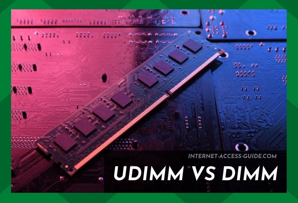
Well, you’re in the right place. So, do you want to learn about DIMM (dual in-line memory module)?
DIMM is integrated into the memory slots of the motherboard. They can be named RAM sticks or UDIMM too.
DIMM is comprised of dynamic RAM integrated circuits on the circuit board. DIMM is regularly used for personal and workplace computers, in addition to servers.
With the launch of the Pentium processor by Intel, SIMMs were replaced by DIMMs. Often, SIMM (single in-line memory module) is called the predecessor of DIMM.
SIMMs had redundant contacts on both sides, whereas DIMM is uniquely designed with a separate electrical contact on either of the modules.
DIMMs are designed with a 64-bit data plan as opposed to the 32-bit data path of their predecessor. With the advent of the Pentium processor, the need for matched pair integration of 64-bit bus width arose, but SIMMs weren’t up to coping with this.
Consequently, DIMMs were created to meet this demand. In addition, the 64-bit data path ensured faster data processing and data transfer when compared to that offered by SIMM.
Over the years, DIMM has become the standard form of computer memory. DIMM is installed on the motherboard and stores information in different memory cells.
UDIMM vs DIMM
For years tech geeks have wondered how UDIMM and DIMM are related.
DIMM is basically the dual in-line memory module which is the unregistered memory configuration.
In addition, DIMM is usually referred to as ‘conventional memory.’ Now, there are four basic types of DIMM out there:
- UDIMM – unregistered and unbuffered memory
- RDIMM – registered memory
- SO-DIMM – the basic laptop RAM
- FBDIMM – fully buffered memory
UDIMM is the normal RAM and unbuffered DIMM. This is the memory chip extensively used in laptops and desktop computers.
These UDIMMs offer a faster performance rate. This memory configuration is reasonably priced, but there might be a compromise on stability.
For better insights, we have designed this article, as such:
- sharing information about DIMM,
- its architecture,
- and how different factors can impact the latency of your computer memory.
Shall we begin?

Feature 1: Architecture of DIMM
As we have already mentioned, DIMM is the printed circuit board integrated with SDRAM and or DRAM integrated circuits.
However, there are other components that affect the performance and outline the functionality of DIMM. Please read on to learn of its features.
Feature 2: Cooling
The density of the chip was basically incremented to enhance the performance standards, promising a better generation of clock speed but more heat as well.
Previously, 16GB and 8GB chips were used, but they weren’t optimizing the heat development.
However, when the chip density was enhanced to 64GB, the reduction of heat became crucial.
Heat reduction technologies were developed by tech manufacturers to help minimize the heat generation from DIMMs.
Cooling fins were included for excess heat venting. The heat was vented out from the motherboard into the exit-way of computers.
Feature 3: Memory Ranks
The latest DIMMs have been designed with independent DRAM chipsets, also known as memory ranks.
These ranks lead to DRAM page initiation, which produces a better performance rate.
It is pretty clear that ranks are connected to a similar address while creating a dense memory for the processors. In contrast, the processors don’t access the ranks for identical operations.
Processors are empowered with interleaving that helps utilize the ranks through different operations.
The users can write to one rank, but reading will be from another outlet.
Upon completion of operations, DRAM flushes the data. In this queue, single channels can cause stalling in the pipelines.
Feature 4: Channel Memory
When it comes to DIMM, single-channel memory is the minimal prerequisite for communication with the processor.
Consequently, the 64-bit channels are designed through dual-channel memory, xx” for the quad-channel and xx for the triple-channel.
But it’s essential to outline that DIMM technology doesn’t signal multi-channel memory.
Feature 5: SDR SDRAM
The signal data rate of DIMM was designed way back in the 1960s. In this case, speed and performance rate is measured in nanoseconds.
DRAM speeds are enhanced through SDRAM, posing synchronization changes to the clock timing in the CPU.
This technology tends to activate quickly while determining the accurate time for data processing.
However, there are zero delays for CPU processing.
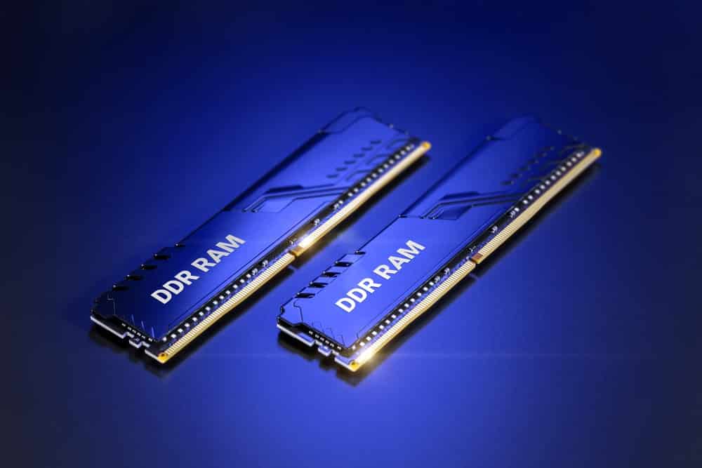
Feature 6: DDR Generations
There are 4 generations of DIMM and DDR – DDR, DDR3, DDR2, and DDR4.
- The DDR2 was designed to speed up the transfer rate while buffering out the first generation.
- DDR3 helps enhance performance while posing a reduction in power consumption.
- Last but not least, DDR4 not only reduces the voltage but enhances the performance and transfer rate.
Moving on to the DIMMs, there are single ranks designed with high capacity.
On the other hand, processors will parallelize rank modules and memory requests.
In the section below, we have added multiple factors that can impact the memory latency with DIMM within a computer system. Take a look!
Feature 7: Speed
With fast DIMM speed, the latency rate will be lower, leading to loaded latency.
The latency rate is increased when memory requests are sent constantly, staying strong for execution.
Faster DMM speeds lead to quick memory control. With such speeds, queued commands are processed quickly.
Feature 8: Ranks
With DIMM and DDR4 memory speed, the loaded latency is increased in increments according to the ranks.
Higher rank speed produces greater capability for processing memory requests.
In addition, it helps reduce the request queues size while enhancing the ability to control the refresh commands.
However, it tends to reduce the loaded latency by multiple ranks. When the channel ranks are increased from four, loaded latency increases.
Feature 9: CAS
CAS is designed as the column address strobe that tends to represent the DRAM response time.
The number of clock cycles is specified, such as 13, 15, and 17.
The column address is designed on the bus but has unloaded and loaded latency measurements.
Feature 10: Utilization
The memory bus utilization, when increased, is less likely to change the low read level of latency.
This is reduced on the memory bus. Users need to write and read down the commands manually.
However, the same amount of time is required to complete these commands, irrespective of the volume of traffic.
When utilization is increased, the memory system latency is increased as queues are jam-packed with the latency, incorporated into the memory controller.